
Deep dive
PRC-029-1 ride-through models: what a portfolio of assessments taught us about PSS/E and PSCAD models
What a portfolio of PRC-029-1 assessments taught us about PSS/E and PSCAD ride-through models: the issues that cost the most time, how we resolved them, and how to avoid them.
GridStrong engineering, November 2026. Written for engineers who build, review or submit IBR ride-through models.
Intro
What PRC-029-1 is about and why it became mandatory. NERC PRC-029-1 requires each Generator Owner to design and operate its inverter-based resources (IBRs) so that every IBR rides through the voltage and frequency excursions inside the "must Ride-through zone" of Attachments 1 and 2 (R1 and R3), keeps exchanging current and supporting voltage while it does so (R2), rides through rate-of-change-of-frequency up to 5 Hz/s averaged over at least 0.1 s (R3), and documents any hardware limitation that prevents this (R4). Voltage criteria are measured at the high side of the main power transformer on the nominal transmission voltage base; instantaneous trip settings with less than one cycle of filtering are not permitted, and frequency is measured over several cycles, never as a single point. The standard exists because, in the disturbances NERC analyzed, IBRs reduced output, ceased current or tripped on their own protection and controls rather than on the fault itself, and in aggregate that behavior became a reliability gap. FERC Order No. 901 of October 19, 2023 directed NERC to close that gap; NERC filed PRC-029-1 in November 2024, FERC approved it in Order No. 909 on July 24, 2025, and the standard became effective on October 1, 2026 for BES IBRs. PRC-029-2 superseded it on the same date; the revisions concern Requirement R4 and a new Attachment 1 Item 12 (see Body item 2), so the ride-through tables and the R1 to R3 obligations our projects were assessed against are the ones in force today. Applicable non-BES IBRs (the Category 2 registrants described in Body item 2) have until the later of January 1, 2027 or the effective date for the design elements of R1 to R3, and IBRs in service by the effective date have twelve months from it to submit R4 hardware-limitation documentation.
The common issues we found. We logged every issue that cost time on our completed PRC-029 projects. Figure 1 shows how the model-related issues divide into ten families; the share of each family is its number of occurrences divided by the total number of model-related issues logged across all projects.
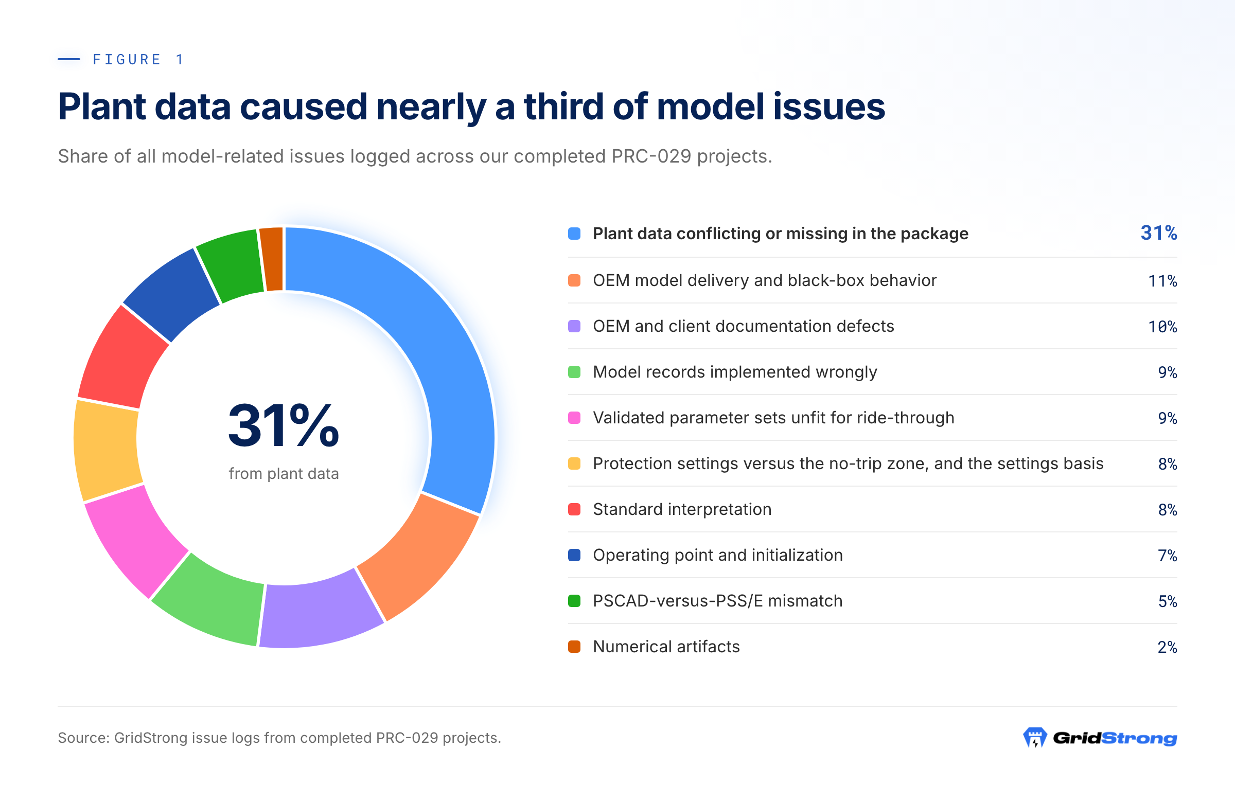
- Plant data conflicting or missing in the package (31%). Two to six values for one quantity (nameplate, transformer impedance, droop settings, tap, unit count, capacitor bank), no usable power-flow case, settings exports covering part of the fleet, plant-controller narratives that contradict the controller export.
- OEM model delivery and black-box behavior (11%). No project electromagnetic-transient (EMT) model, generic test benches with default parameters, a package for a different product, several model generations for one inverter, libraries compiled for another compiler or PSS/E version, and ride-through modes whose entry and exit logic is not published.
- OEM and client documentation defects (10%). Capability reports for other ratings, blank settings tables, a mis-cited hardware-limitation column, datasheet tables that contradict the delivered deck, PDF text layers that shift columns.
- Model records implemented wrongly (9%). Relay records that cannot act (an unused bound at zero, a bus that does not exist, a block on the wrong aggregate), transposed stages, a deadband typed in hertz where per unit is expected, a case cloned from another plant.
- Validated parameter sets unfit for ride-through (9%). MOD-026 sets with the reactive-current injection path disabled, plant-controller voltage filters of several seconds, placeholder zeros in the current-limit tables, reference clamps at the edge of the continuous region.
- Protection settings versus the no-trip zone, and the settings basis (8%). As-left stages inside the must ride-through zone, and three candidate sets per plant (as-left, OEM maximum, target configuration) with no decision on which the model represents.
- Standard interpretation (8%). Terminal versus main-transformer measurement point, per-unit base, applicability to legacy turbine types, boundary values, when R2.1.3 reactive priority applies.
- Operating point and initialization (7%). Terminal voltage 5 to 10% away from the point of measurement under full lagging or leading dispatch, reactive limits on inconsistent bases, plant controllers regulating a bus they cannot move, shunts netted away.
- PSCAD-versus-PSS/E mismatch (5%). Different bases, taps and meter buses in the two models, structural differences between generic and vendor models, and responses that disagree in the high-voltage cases.
- Numerical artifacts (2%). Non-convergence at near-zero voltage, fictitious bus frequency during deep dips, drive-train drift in long runs.
The lessons we learned.
- The data package decides the schedule. Nearly a third of all model issues were conflicting or missing plant data, and every project had some.
- Where you measure decides pass or fail. Settings live at the inverter terminal; the standard measures at the main-transformer high side, and the two differ by 5 to 10% at full reactive dispatch.
- A validated MOD-026 model is not a ride-through model. It was fitted to a reference step, never to a fault, and the parameters that govern fault response were never fitted.
- The protection basis must be decided before the first run. A stage the hardware can be re-set to clear is a settings change; one it cannot clear is an R4 item that needs the OEM's document, not our assumption.
- OEM EMT models arrive late, generic or not at all, and black-box behavior must be documented by the OEM, not tuned around.
- PSS/E and PSCAD alignment is a bases-first job. Some differences are structural; they are documented, and the EMT result governs.
- A numerical artifact is never fixed by editing an as-left relay value.
What to do to avoid similar issues under any new guideline.
- Put the standard's own text, measurement point and per-unit base on one page before the first file is opened, and settle applicability and the protection basis with the owner on that page.
- Build to discover: try to fill every model field on day one, and send the gap and conflict list before anyone thinks the package is complete.
- Keep the validated parameter set as the base case; label every departure as a sensitivity for the OEM to confirm.
- Run a flat case with no disturbance before any ride-through case, in both engines.
- Request from the OEM, with the first data request: the project EMT model and parameter set, the model generation matching installed firmware, the compiler and snapshot compatibility, and a site-specific capability letter.
- Align the two engines on bases, taps, meter bus and dispatch before comparing any response.
Body
1. The issues in detail, how general they were, and how we dealt with them
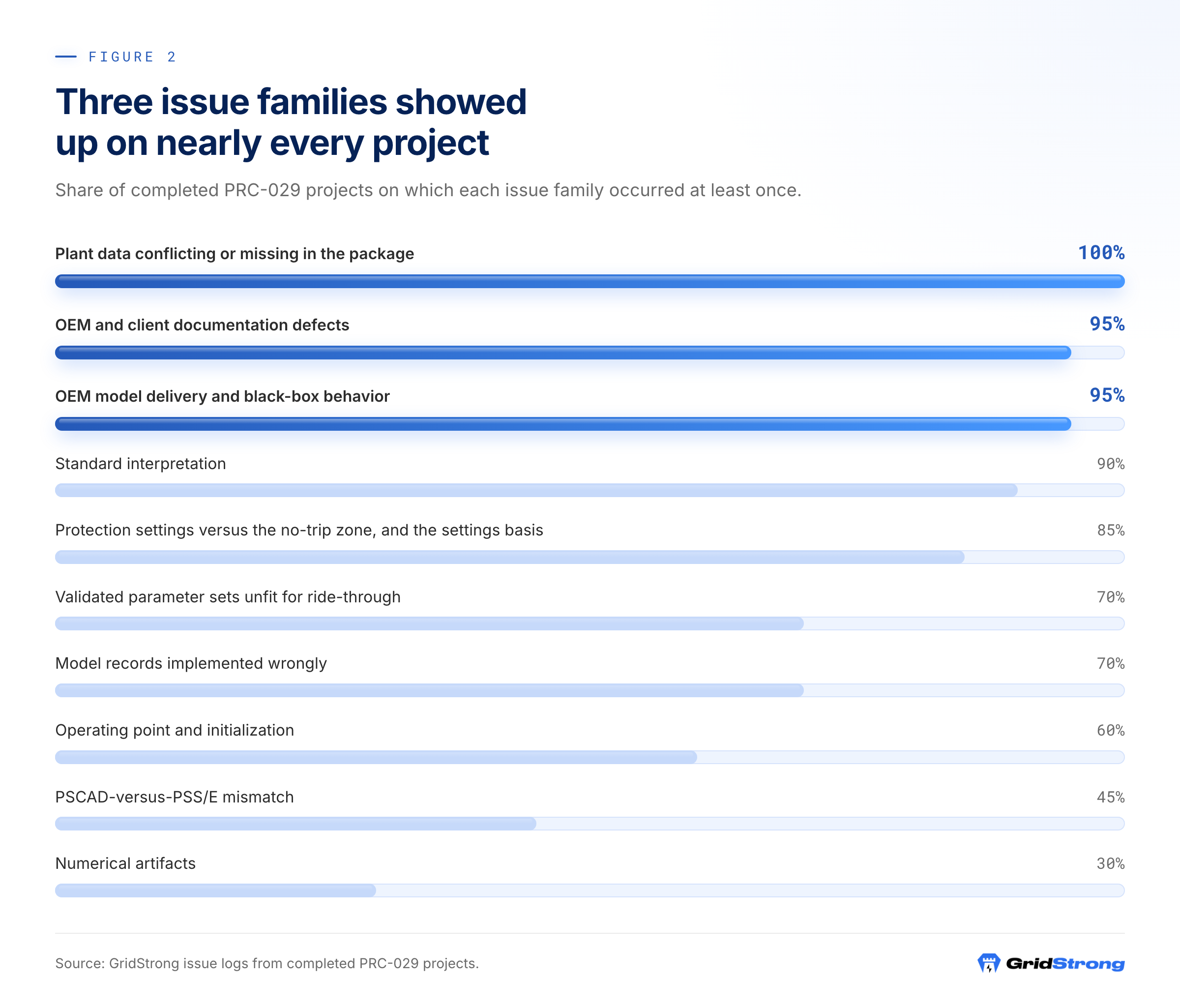
Figure 2 shows how widely each family occurred. Three families touched nearly every project; the engine-mismatch and numerical families were the least common but among the most expensive per occurrence because each one cost a full suite of re-runs.
1.1 Issues or missing items in the PSCAD model, and how we resolved them
| Issue | Share of projects | How we resolved it |
|---|---|---|
| No project-specific EMT model: nothing delivered, a generic sample system, a package for a different inverter product, or a hybrid demo case | 70% | Compliance evidence rested on the PSS/E model with the EMT scope recorded as not performed; where a proxy block had to be used, its voltage and MVA base mismatch was stated in the model header and the base question was put to the OEM; the project model was requested from the OEM with a named parameter set. |
| Demo or template defaults carried into the plant case: sample plant base and unit count, grid source and short-circuit ratio defaults, controller time constants far faster than the plant controller, a spare inverter module with default protection left in, a storage branch left live, the type selector on the wrong product code | 35% | A parameter sheet derived from the PSS/E dyr was applied to the PSCAD case field by field, and unused modules and branches were deleted rather than disabled. |
| Undocumented black-box behavior: a ride-through mode that latches on terminal voltage and leaves a dead band, a frequency time compensation that makes a delayed stage act instantaneously, high-voltage control modes with unpublished thresholds, a measurement signal that overshoots for a millisecond at a voltage step and trips an instantaneous element | 40% | Sensitivity runs on an untouched copy of the OEM parameter files, override-only; mode thresholds placed outside the terminal-voltage range seen in the continuous region; a short pickup delay on the instantaneous stage held as an assumption and put to the OEM; written questions to the OEM on each mode's entry and exit signal, hysteresis and time compensation. |
| Compiler, library, version and time-step problems: libraries built for a different Fortran than the manual states, two uncontrolled project versions with conflicting plant-controller parameter files, snapshots bound to one compiler or pointing at a developer's folder, a time step so small that a ten-second case took about an hour | 35% | The variant that compiled was used; where the time step made the full case set impractical locally, local runs were limited to single cases; the OEM was asked for the controlled release, compiler version and snapshot compatibility. |
| The plant not at its dispatch point when the disturbance starts: the plant voltage loop integrates toward the setpoint with a time constant of tens of seconds, a converter model still in start-up when the profile begins, pre-event reactive power several percent off | 20% | The voltage reference was set per polarity from the droop relation and the disturbance moved to after the loop had settled; pre-event P and Q were then checked against the PSS/E dispatch. A steady-state snapshot was recommended but is not yet standard practice. |
| Protection in the PSCAD model not matching the as-left settings or the PSS/E model | 15% | The protection tabs were set from the same settings export and the same protection basis as the dyr where the OEM case allowed it; where a bundle had been labeled by the wrong basis, the basis was recorded in the package notes. |
| Build and runtime errors from edited demo cases: floating signals, two writers on one signal, an ungrounded subsystem | 15% | Errors traced in the project XML one by one; disabled subsystems removed outright. |
1.2 Issues in the PSS/E model, and how we resolved them
| Issue | Share of projects | How we resolved it |
|---|---|---|
| No usable plant power-flow case: dyr only, an OEM sample system, or a stale pre-synchronization equivalent | 60% | The case was rebuilt from the as-built single line, factory tests and nameplates, with every assumed value marked in the header. |
| Validated MOD-026 set unfit for ride-through: injection path disabled, plant filters of several seconds, placeholder zeros in current-limit tables, reference clamps at the continuous-region edge | 65% | Departures were made only where a case could not otherwise be judged and were recorded parameter by parameter in the version notes and the parameter sheet, with the OEM asked to confirm them; the plant filter was shortened, the injection path enabled with generic thresholds, and placeholder points made monotonic. |
| Protection records missing, mis-implemented or on the wrong bus: an unused bound at zero that trips at the first sample, relays on a non-existent bus, a block pasted onto the wrong aggregate, a transposed over-voltage stage, frequency records absent | 50% | Sentinel bounds restored, relays repointed, stages re-derived from the datasheet, and trip times checked by arithmetic against the stage settings. |
| As-left stages inside the must ride-through zone, with the settings basis undecided | 70% | Two dyr variants named by protection set (as-left and OEM maximum), the derivation of the maximum set in the header and the as-left values kept as comments on each record; the owner asked to confirm which set the plant will carry. |
| Terminal voltage 5 to 10% away from the point-of-measurement voltage under lagging or leading dispatch, so terminal-referenced stages trip inside the zone | 65% | Transformer taps confirmed from the nameplate tap table and the owner, the main-transformer ratio set to the study value, and the offset stated per dispatch so each stage could be screened against it. |
| Reactive limits on inconsistent bases across the raw file, the electrical-control record and the plant-controller record; lagging cases starting at the limit with suspect initial conditions | 50% | One MVA base carried through raw, dyr and plant-controller data; the three limits made consistent; dispatch set within the plant's capability. |
| Regulated bus, monitored branch or freeze threshold wrong: the plant controller regulating the swing bus or a bus it cannot move, the raw regulated bus different from the dynamic-model bus, the branch orientation reversed | 45% | Regulated bus made the plant-controller bus in both files, branch orientation set by the measured sign, freeze threshold set, and each plant controller given its own metered branch on multi-transformer plants. |
| Non-convergence and fictitious bus frequency during near-zero voltage, tripping frequency relays that have no voltage supervision | 50% | On the first projects a frequency record was commented out or a pickup lengthened to get past the artifact, a practice we have since dropped; the EMT model was made the frequency engine of record and frequency trips inside a near-zero-voltage interval were reported as numerical artifacts. The recommended practice is to monitor frequency relays at the point-of-measurement bus with a multi-cycle filter. |
| Switched shunts and reactive netting: power-factor capacitors netted into zero reactive power, a bank with a zero control band, a template shunt with no bank on site, a disabled bank deleted | 40% | Banks modeled as locked shunts and switched per case; where power-factor capacitors had been netted away, an explicit aggregated shunt was recommended before re-initializing; a disabled bank is now kept in the case out of service rather than deleted. |
| Validated dyr in an older PSS/E user-model format: suffixed model names, changed constant counts, comment prefixes that break the loader, DLLs built for older versions only | 55% | Records renamed to library models, constant layout checked against the model library before the first run, generic models used where no current DLL exists. |
| Network data in the validated case contradicted by nameplates and tests: transformer reactance far off, collector resistance several times too low, a gen-tie never loaded, resistances in a workbook's reactance column, a dynamic reactive device in no model | 55% | Rebuilt from factory tests and nameplates; the collector equivalent recomputed by n-squared aggregation, reproducing the published value first to isolate the error. |
| Plant-controller mapping: droop with several values on different bases, PID form unstated, a reactive-power filter taken as the voltage filter, a narrative crediting the wrong controller | 70% | A field-by-field map from the PLC program to the plant-controller model with the droop base stated beside the number; the PLC project requested rather than a narrative. |
| Drive-train drift in long runs on wind models: an undamped single-mass drive train with the torque model's speed reference above its breakpoint | 10% | Rotor speed and torque channels checked in a run of several minutes before judging any recovery; torque rating set per machine. |
1.3 How we made sure PSS/E and PSCAD were almost aligned, and what typically breaks that alignment
Alignment was done in a fixed order. First the plant data: one MVA base, the same unit count, the same transformer impedances and taps, the same collector equivalent, the same grid strength, and the point of measurement on the same bus in both models. Second the dispatch: both engines initialized at the same pre-event active and reactive power at that bus, which in PSCAD means a per-polarity voltage reference and a disturbance start after the plant loop has settled. Third the protection: the same settings basis, the same stages on the same buses. Only then the controllers: plant-controller gains, limits and filters mapped from the same PLC source, and the inverter's ride-through thresholds in PSCAD set to the same voltages as the generic model's. Every case was then compared on active power, reactive power and point-of-measurement voltage, and every residual difference was either traced to a parameter or recorded as structural.
| What broke alignment | Share of projects | What we did |
|---|---|---|
| Different bases, taps or meter buses between the two models, including one engine metering on the low side of the main transformer and the other on the high side | 40% | Fixed before any controller comparison; a 5% difference in terminal base moves the high-voltage margin by the same 5%. |
| OEM demo defaults left in the PSCAD case | 35% | Stripped with a parameter sheet derived from the dyr. |
| Structural differences between generic and vendor models: a current-only limit against a fixed apparent-power limit, one injection gain for low and high voltage, a current-limit table against a latching ride-through mode | 35% | Documented as known limitations of the generic representation; the EMT result governs where a result depends on them. |
| A response that differed between the engines in the high-voltage or small-disturbance cases | 30% | The disagreement written into the report with its cause and the case dispositioned provisionally on one engine, with the question put to the OEM; our rule since is that the EMT result governs rather than tuning one engine to the other. |
| Different protection sets or bases in the two models | 20% | Both models built from the same export and labeled by the same basis. |
| PSCAD not at the PSS/E dispatch when the disturbance started | 20% | Initialized to the PSS/E dispatch with a per-polarity voltage reference and a later disturbance start. |
2. New regulations for IBR interconnection, PRC-029 Category 2, and which findings carry over
PRC-029-1 is one of the Order No. 901 standards, and more are already in force or in flight. The Milestone 2 set is PRC-028-1 (disturbance monitoring and reporting for IBRs), PRC-029-1 (ride-through) and PRC-030-1 (unexpected IBR event mitigation), filed together and approved by July 2025; PRC-024-4, approved with PRC-029-1, continues to cover synchronous generators, Type 1 and Type 2 wind plants and synchronous condensers. The Milestone 3 package was approved by FERC on February 19, 2026: MOD-026-2 (verification and validation of dynamic models and data, replacing MOD-026-1 and MOD-027-1), MOD-032-2 and MOD-033-3 (modeling data and system model validation), and the IRO-010-6 and TOP-003-8 data specifications. In approving MOD-026-2, FERC declined to remove the exclusion for legacy facilities with no remaining OEM support for EMT models, and stated that the standard does not relieve interconnection customers of their tariff obligations to provide validated EMT models. Milestone 4 revises the planning and operating study standards: NERC adopted TPL-001-6 on October 8, 2026 and filed it with FERC on November 2, 2026, against the November 4, 2026 deadline in Order No. 901, with FAC-011-5 and TOP-003-9 filed separately.
Two things are often called "PRC-029 Category 2", and they are different.
- Category 2 registration. Category 2 Generator Owners and Operators are entities with non-BES inverter-based generating resources that have, or contribute to, an aggregate nameplate capacity of 20 MVA or more connected through a system designed primarily to deliver that capacity to a common point of connection at 60 kV or above; battery and fuel-cell facilities count, and aggregation across a shared point of connection counts. NERC's practice guide required these entities to register by May 15, 2026. PRC-029 applies to them, PRC-029-2 since October 1, 2026: the same Attachments and the same R1 to R3 obligations, with the design elements of R1 to R3 due by the later of January 1, 2027 or the effective date. These plants are smaller by definition, and the smaller and older plants in our own portfolio were the ones that arrived with a dyr only, no EMT model and thin OEM support, so the findings that carry over most are the first three families in Figure 1: the data package, the OEM model delivery, and the documentation defects, followed by the measurement-point lesson, because distribution-connected and sub-transmission plants have larger terminal-to-point-of-measurement offsets.
- PRC-029-2. Project 2025-05 revises the standard in response to Order No. 909's directives. The NERC Board adopted PRC-029-2 on August 18, 2026 and NERC petitioned FERC for approval on August 28, 2026. The revision narrows and clarifies Requirement R4: a limited pathway for "long-lead" projects with executed procurement contracts and interconnection agreements that were not in service by the PRC-029-1 effective date, clarification of the documentation that supports a hardware-limitation exemption, and a new Attachment 1 Item 12 that can exempt HVDC-connected IBRs with choppers from Items 7 to 9 when the limitation is documented and coordinated. FERC approved PRC-029-2 shortly before October 4, 2026, and NERC states that it became effective on October 1, 2026, at which point PRC-029-1 retired.
What carries over to all of these is the model itself. PRC-028-1 provides the disturbance recordings and PRC-030-1 the event analyses against which MOD-026-2 and MOD-033-3 expect the models to be validated, and the R4 pathway in either version of PRC-029 assumes an OEM document that names the installed configuration. The three findings that help most are therefore: a validated set must be checked for the parameters the validation never exercised before it is used for anything else; the protection basis and the OEM capability letter are evidence, not assumptions; and the two engines must share bases, dispatch and protection before either result is quoted.
3. Large-load (data-center) interconnection: how the PRC-029 framework and our Dashboard apply, and what the lessons make smoother
Large loads are moving onto the same regulatory track that IBRs took. On October 23, 2025 the Secretary of Energy directed FERC under Section 403 of the DOE Organization Act to consider large-load interconnection reforms; FERC opened docket RM26-4-000 on October 27, 2025. The proposal preliminarily defines large loads as those above 20 MW connecting directly to FERC-jurisdictional transmission, would make them responsible for the network upgrades their studies assign, and directs NERC to review whether new registration categories and standards are needed. On June 18, 2026 FERC chose show-cause orders to all six RTOs and ISOs over a single nationwide rule, requiring each to justify or reform its large-load procedures. On the reliability side, NERC's Large Loads Working Group identified the lack of predictable ride-through performance for large loads as a gap in the existing standards, is proposing new registered entity types (Computational Load Owner and Operator), has a white paper on large-load disturbance performance and ride-through recommendations targeted for December 2026, and has submitted a Standard Authorization Request for ride-through and post-fault active-power recovery requirements for computational loads that cites the ERCOT NOGRR 282 voltage ride-through requirements as a minimum baseline.
The PRC-029 framework transfers almost directly. A ride-through requirement for a load is the same test as for a generator with the sign of the power reversed: hold the point-of-interconnection voltage and frequency on a defined profile, record demand during and after the excursion, and judge the result against a voltage-time table and a recovery time. Our Dashboard already runs that test on PSS/E and PSCAD models of generating plants against the PRC-029-1 tables and the ride-through cases in lagging and leading dispatch; the same profiles, the same two engines and the same reporting apply to a load model, with the table swapped for the one the load standard adopts and the pass criterion changed from "keeps injecting" to "keeps consuming and recovers". The parts of a data-center model that decide ride-through, the uninterruptible-power-supply transfer logic, the drive and server power-supply under-voltage limits and the on-site generation and storage controls, are the load-side equivalents of the inverter ride-through modes we spent most of our time on.
The lessons that make large-load interconnection smoother are the ones that cost us the most time on IBRs: fix the measurement point and the per-unit base on one page before modeling, because load-side protection sits behind one or two transformers exactly as inverter protection does; decide which settings basis the model represents, because a facility's as-left under-voltage settings and its vendor's capability are different documents; get the vendor's model and its controlled release, compiler and parameter set with the first data request; and align the EMT and positive-sequence models on bases and dispatch before comparing them. A facility that arrives with one solved case, one settings export for every unit and one capability letter per vendor will clear a load ride-through study in a fraction of the time our IBR projects took.
4. How our Dashboard helps the engineer
The Dashboard is the framework we ran every project on, and its value is in what it does for the engineer rather than in what it replaces.
- It reads the whole client data package, builds a findings register that marks each required item as documented, inferred or not found, lists every conflict between sources with both values and their documents, and drafts the client and OEM question list by recipient and priority, so the engineer starts with the gap list instead of discovering gaps one field at a time.
- It drafts the dynamic model records from the documents and the settings export, with every assumed value flagged in the header, so the engineer reviews rather than types.
- It runs the complete PRC-029-1 case suite on the uploaded PSS/E and PSCAD packages: the low- and high-voltage ride-through, consecutive-fault, small-voltage-disturbance and active-power-recovery cases in lagging and leading dispatch in both engines, with the frequency, rate-of-change-of-frequency, phase-angle-jump and asymmetrical-fault cases in the EMT engine.
- It extracts the protection settings and rating data from the uploaded models and shows them beside the settings export, so a model that does not carry the plant's protection is visible before any case runs.
- It evaluates every case against the sub-requirements of R2 with the measured quantities on the page, compares the PSS/E and PSCAD responses case by case, and keeps every channel of every run with its solver log in a queryable results store, so a question about any result can be answered from the stored signals rather than from a screenshot.
- It keeps every uploaded model package and run under its own identifier and drafts the compliance report from the results, so the report, the model and the run that produced it stay linked.
5. Our suggestions on how to avoid similar issues in the future
- Start from the standard's text. Put the measurement point, the per-unit base, the applicable table, the boundary conventions and the R2.1.3 scope on one interpretation sheet, and agree it with the owner before the first file is opened.
- Send the data request before the package is cut, and ask for the items that were missing most often: the solved power-flow case of record, a dated settings export for every unit with the export options stated, transformer factory tests and the nameplate tap tables, the complete PLC program, the OEM capability letter naming the installed configuration, the interconnection short-circuit data, and the collector cable schedule.
- Build to discover. Attempt to fill every field the three models need on day one, report every candidate value with its source, and never resolve a conflict silently.
- Decide the protection basis in writing before the first run, as-left, OEM maximum or target, and name every model file by its basis. Screen the settings export against Attachments 1 and 2 the same day.
- Keep the validated parameter set as the base case. Diff it against the generic ride-through defaults, label every departure as a sensitivity, and put the parameter question to the OEM in writing before any result goes to the owner.
- Solve the lagging and leading dispatch and read the terminal voltage before any dynamic run; screen every stage, threshold and clamp with that offset; confirm transformer taps from the nameplate table and the owner, not from a drawing.
- Fix one MVA base and write the reactive limit on it in the raw file, the electrical-control record and the plant-controller record; dispatch within the plant's real capability.
- Run a flat case with no disturbance in both engines before any ride-through case, and a run of several minutes on wind models, and check that P, Q, voltage, speed and torque stay where they started.
- Load and document every dyr against the model library before it runs: every relay bus exists, unused bounds are sentinels, constant layouts match, deadbands and admittances are on the right base.
- Ask the OEM, with the first data request, for the project EMT model, the parameter table matching the installed firmware, the controlled release with its compiler and snapshot compatibility, the recommended time step, and each ride-through mode's entry and exit signal, hysteresis and time compensation.
- Strip the demo from any OEM PSCAD case with a parameter sheet derived from the dyr, delete rather than disable unused subsystems, and compile after every structural edit.
- Align the two engines in order: data, dispatch, protection, controllers. Initialize PSCAD from the PSS/E power flow and snapshot it. Record every structural difference, and let the EMT result govern where a result depends on it.
- Monitor frequency relays at the point-of-measurement bus with a multi-cycle filter and log non-converged steps per version; never edit an as-left relay value to survive an artifact.
- Issue two deliverables where the basis is undecided, the validated set as delivered and the capability case with every departure attributed, and map every result to the sub-requirement it addresses.
Conclusion
The physics of ride-through was rarely the obstacle. Nearly a third of the model issues we logged were conflicting or missing plant data, and nearly every project had an OEM model that was late, generic or undocumented. The two technical findings that decided the most results were the terminal-to-point-of-measurement offset, which puts terminal-referenced protection stages inside the zone under full reactive dispatch, and validated MOD-026 parameter sets that were never fitted to a fault. Both are found in the first day by solving the two dispatches and diffing the validated set against the ride-through defaults. The same discipline, one interpretation sheet, one data request, one protection basis, one MVA base, a flat run first and bases-first alignment between engines, carries unchanged to PRC-029-2, to the Category 2 plants whose design deadline falls on January 1, 2027, to the MOD-026-2 validation regime, and to the load ride-through requirements now being written for data centers.
GridStrong is an engineering consultancy for inverter-based resource compliance and modeling. The published standards govern; this article records lessons learned and is not compliance advice for a specific facility.
Select Citations
- (NERC): Reliability Standard PRC-029-1, Frequency and Voltage Ride-through Requirements for Inverter-based Resources (Board approved October 8, 2024)
- (FERC): Order No. 909, Reliability Standards for Frequency and Voltage Protection Settings and Ride-Through for Inverter-Based Resources, July 24, 2025 (Docket RM25-3-000)
- (NERC): Petition for Approval of Proposed Reliability Standard PRC-029-2, August 28, 2026
- (NERC): Project 2025-05 Ride-Through Revisions, Implementation Plan and Technical Rationale, April 2026 (Technical Rationale)
- (American Public Power Association): FERC Approves NERC Reliability Standard on Frequency and Voltage Ride-Through Requirements for IBRs, October 4, 2026
- (NERC): CMEP Practice Guide, Application of the Registration Criteria for Category 2 Generator Owner and Generator Operator Inverter-Based Resources
- (FERC): Order Approving Inverter-Based Resources and Generators Modeling Reliability Standards, February 19, 2026 (Dockets RD26-1-000, RD26-2-000, RD26-3-000), Federal Register, February 24, 2026
- (Texas RE): IBR Standards Under FERC Order 901, March 2026
- (NERC): Petition for Approval of Proposed Reliability Standard TPL-001-6, November 2, 2026
- (FERC): Docket RM26-4-000, Interconnection of Large Loads to the Interstate Transmission System (Notice Inviting Comments, October 27, 2025); FERC show-cause orders to the six RTOs/ISOs, June 18, 2026 (Dockets EL26-67-000 to EL26-72-000)
- (NERC): Large Loads Frequently Asked Questions, and Large Loads Working Group, Standard Authorization Request: Reliability Standards to Address Computational Load Disturbance Performance (Standard Authorization Request)
Applying this to your plants?
Bring the question to a GridStrong engineer. We will walk through how it applies to your plants, your models and your deadlines.